Reese Electric Brake Controller Manual: A Comprehensive Guide
Welcome! This manual expertly guides you through setup and operation of your Reese Trailer Brake Controller Wiring Diagram, maximizing performance and ensuring safe towing experiences.
Reese has long been a trusted name in towing solutions, and their electric brake controllers are designed to provide reliable and responsive braking for your trailer. This controller, detailed in this manual, offers proportional braking, meaning it applies the trailer brakes in relation to the tow vehicle’s braking – enhancing safety and control.
Understanding your Reese brake controller is crucial for safe towing. It’s more than just a device; it’s a vital component of your vehicle’s safety system. This guide will walk you through everything from installation and setup to operation and troubleshooting. Reese controllers are compatible with a wide range of vehicles and trailers, offering versatility and convenience. Proper installation and adjustment, as outlined herein, are paramount for optimal performance. Remember, Reese, as your trusted teacher, guides you to safe towing!
Understanding Electric Trailer Brakes
Electric trailer brakes are a crucial safety feature, working in conjunction with your tow vehicle’s brakes to provide effective stopping power. Unlike hydraulic brakes, electric brakes utilize electromagnets to engage the brake shoes. When the brake controller sends a signal, these magnets activate, pressing the shoes against the brake drums.
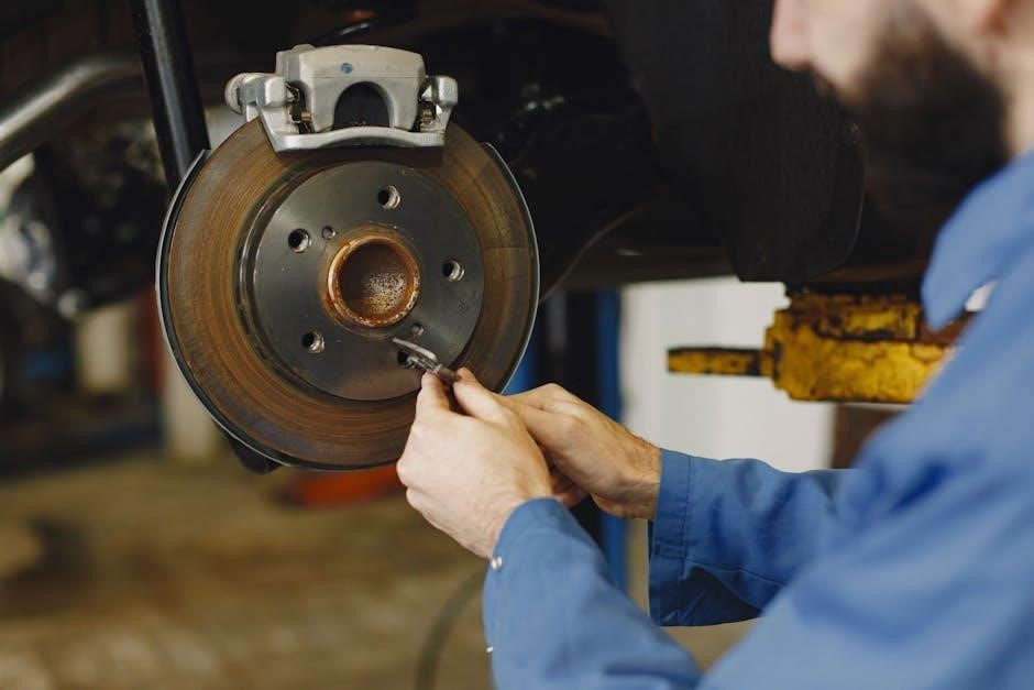
The intensity of the electrical signal determines the braking force applied. A stronger signal means harder braking. This is where the proportional control of a Reese controller becomes vital, mirroring your vehicle’s braking effort. Understanding metric thread sizes and systems like ABS, while related to vehicle mechanics, are separate from the core function of electric trailer brakes. Proper maintenance, including drum inspection and shoe replacement, is essential for optimal performance and safety. This system ensures controlled stops, even with heavy loads.
Safety Precautions and Warnings
Prioritize safety! Improper installation or operation of your Reese brake controller can lead to accidents. Always disconnect the controller from the vehicle’s power source before working on the wiring. Ensure all connections are secure and properly insulated to prevent shorts.
Never exceed the trailer’s maximum braking capacity. Regularly inspect the trailer brakes for wear and tear, and address any issues promptly. Be aware that algorithms like ADFGVX, while interesting, are irrelevant to brake system safety. Familiarize yourself with the controller’s manual override function for emergency situations. Always test the brakes at low speeds before embarking on a journey. Ignoring these precautions could compromise the braking system, potentially causing loss of control and serious injury; Safe towing requires diligence and understanding.

Installation Guide
Begin installation! This section details wiring diagrams, mounting procedures, and connections to both your tow vehicle and trailer for optimal brake controller functionality.
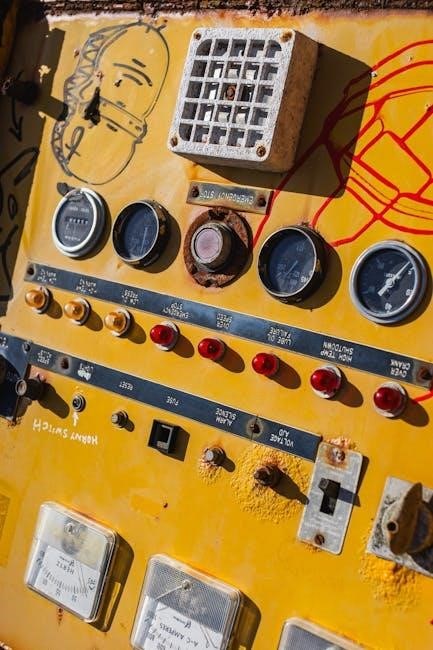
Wiring Diagram Overview
Understanding the Connections: The Reese brake controller requires careful wiring for proper function. Typically, you’ll need to connect to the vehicle’s brake light circuit (often a four-way flat connector), a 12-volt power source, and ground. Refer to your vehicle’s manual for specific wire colors and locations.
Key Wiring Components: The wiring diagram illustrates the connection points for the brake controller, including the blue wire for electric brake output, white wire for ground, and the red wire for 12V power. Ensure secure connections using appropriate crimp connectors or solder and heat shrink tubing. Improper wiring can lead to malfunction or damage.
Schematic Importance: Always consult the specific wiring diagram included with your Reese controller model, as configurations can vary. Diagrams may also show connections for optional features like manual override or integrated brake gain displays. Double-check all connections before powering on the system.
Controller Mounting Instructions
Optimal Placement is Key: Select a mounting location within easy reach of the driver, yet out of the normal traffic flow within the vehicle. Avoid areas obstructing airbags or vehicle controls. A common location is under the dashboard, ensuring clear visibility of the display.
Secure Mounting Procedure: Utilize the provided mounting bracket and screws. Mark the screw locations carefully, pre-drill pilot holes if necessary, and securely fasten the bracket to the vehicle’s dashboard or a suitable surface. Ensure the controller is firmly attached and doesn’t rattle during vehicle operation.
Angle and Accessibility: Position the controller at a comfortable viewing angle for easy adjustment while driving. Verify that all wiring connections have sufficient slack and are routed safely away from moving parts. A stable and accessible mount is crucial for convenient operation.
Connecting to the Tow Vehicle
Power Connection: Locate the vehicle’s brake light circuit wire – typically found within the wiring harness under the dashboard. Connect the controller’s brown wire to this circuit. This provides power to the controller whenever the brake pedal is pressed, activating the trailer brakes. Ensure a secure and insulated connection.
Ground Connection: Connect the controller’s white wire to a clean, unpainted metal surface on the vehicle’s chassis. A solid ground connection is vital for proper controller function and prevents electrical interference. Verify the connection is free from corrosion.
Wiring Harness Integration: Utilize the provided wiring adapter, if applicable, for a seamless connection to the tow vehicle’s electrical system. Double-check all connections for polarity and security before proceeding. Proper wiring ensures reliable brake control.
Connecting to the Trailer
Trailer Wiring Identification: Locate the trailer’s wiring connector, typically a 7-pin or 4-pin connector. Identify the brake wire – usually blue in color. Confirm this with the trailer’s wiring diagram if available. Incorrect wiring can lead to brake malfunction.
Controller Connection: Connect the controller’s blue wire to the trailer’s brake wire. Ensure a secure and weatherproof connection using a compatible connector. A reliable connection is crucial for transmitting the brake signal.
Ground Verification: Verify the trailer’s ground connection is secure and free from corrosion. A poor ground can cause erratic brake performance. Inspect the trailer’s wiring for damage before connecting. Proper connection ensures safe and effective trailer braking.
Operation and Adjustment
Fine-tune braking! Adjust sensitivity for optimal control, utilizing the manual override when needed, and understand proportional control for smooth, responsive trailer braking performance.
Power On and Initial Setup
Initial Power-Up: Upon connecting your Reese brake controller, the unit will initiate a self-diagnostic sequence, briefly illuminating the display. Ensure the tow vehicle’s ignition is switched to the ‘ON’ position to activate the controller. Observe the display for any error messages; consult the troubleshooting section if issues arise.
Setting Preferences: Many Reese controllers allow for personalized settings. Access the menu – typically via a button press or combination – to configure preferences like display brightness and units of measurement. Refer to your specific model’s detailed instructions for menu navigation.
Trailer Connection Verification: Before driving, confirm a secure connection between the controller and the trailer wiring harness. A properly connected system is crucial for effective braking. The controller should recognize the trailer’s brake signal. If not, double-check the wiring connections at both the vehicle and trailer ends. Proper setup guarantees safe and controlled towing.
Adjusting Brake Sensitivity
Fine-Tuning for Optimal Braking: Adjusting brake sensitivity is crucial for matching the trailer’s braking force to the tow vehicle’s capabilities. Begin with a low sensitivity setting and gradually increase it during a test drive in a safe, open area. Monitor the trailer’s response – it should brake smoothly and in sync with the tow vehicle.
Proportional Control Adjustment: Reese controllers often feature proportional braking. This means the braking force applied to the trailer is proportional to the tow vehicle’s deceleration. Fine-tune the proportional setting to achieve optimal responsiveness without causing jerky movements or premature trailer lockup.
Manual Override Adjustment: Utilize the manual override function to independently apply the trailer brakes. This allows you to assess the trailer’s braking strength at various sensitivity levels. Remember to always prioritize smooth, controlled braking for a safe towing experience. Consistent adjustments ensure optimal performance.
Manual Override Function
Independent Trailer Brake Control: The manual override function provides direct, independent control of the trailer brakes, bypassing the proportional circuit. This is invaluable for testing brake functionality, performing emergency stops, or maintaining control on steep descents. Engage the override by firmly pressing and holding the designated button or lever on the controller.
Testing and Emergency Use: Regularly test the manual override to confirm the trailer brakes are responding correctly. In emergency situations, the override allows you to apply maximum braking force to the trailer, regardless of the tow vehicle’s deceleration.
Controlled Application is Key: Use the manual override cautiously and in short bursts to avoid sudden stops or skidding. Remember to release the override once the desired braking effect is achieved, returning control to the proportional system. Proper use enhances safety and control.
Proportional Brake Control Explained
Synchronized Braking Power: Proportional brake control dynamically adjusts the trailer brake force based on the tow vehicle’s braking intensity. As you apply the brakes in your truck, the controller sends a corresponding signal to the trailer brakes, ensuring synchronized deceleration. This system mimics your braking habits for a natural and safe towing experience.
Smooth and Consistent Stops: Unlike traditional systems, proportional control prevents over-braking or under-braking, delivering smooth and consistent stops. The controller utilizes a sophisticated circuit to monitor deceleration and regulate the trailer’s braking response accordingly.

Enhanced Stability and Control: By maintaining a proportional relationship between the tow vehicle and trailer brakes, this system significantly enhances stability and control, particularly when navigating varying road conditions or hauling heavy loads. It’s a cornerstone of modern trailer braking technology.
Troubleshooting Common Issues
Diagnostic Support: This section provides solutions for typical problems like no power, brake activation failures, erratic performance, and controller display errors – ensuring swift resolution.
No Power to the Controller
Issue: If your Reese brake controller displays no power, begin by verifying the connection at the tow vehicle. Ensure the controller is securely plugged into the designated wiring harness, often located under the dashboard.
Fuse Check: A blown fuse is a common culprit. Locate the inline fuse on the controller’s power wire (typically red) and inspect it for continuity. Replace with a fuse of the exact same amperage rating if necessary. Also, check the corresponding fuse in your vehicle’s fuse box – consult your vehicle’s owner’s manual for location.
Wiring Integrity: Carefully examine the wiring for any signs of damage, such as cuts, crimps, or corrosion. A damaged wire can interrupt the power supply. Repair or replace any compromised wiring sections. Confirm a solid ground connection; a poor ground can also prevent power-up. If problems persist, consult a qualified automotive electrician for further diagnosis.
Brakes Not Activating
Problem: If the trailer brakes aren’t activating despite controller power, start by checking the wiring connection at the trailer. Ensure the connector is clean, secure, and properly mated with the controller’s output; Inspect the trailer’s brake wiring for breaks or corrosion.
Brake Magnets: Verify the trailer’s brake magnets are functioning. Use a test light or multimeter to confirm voltage is reaching the magnets when the brakes are applied. If no voltage is present, investigate the trailer’s brake wiring and connections further.
Controller Settings: Double-check the controller’s output settings. Ensure the sensitivity and gain are appropriately adjusted for your trailer’s weight and braking requirements. A low setting may not provide sufficient power to activate the brakes. Finally, confirm the emergency brake isn’t engaged, as this can override normal braking function.
Erratic Brake Performance
Issue: Experiencing inconsistent or jerky braking? This often points to wiring issues. Thoroughly inspect all connections – at the tow vehicle, controller, and trailer – for looseness, corrosion, or damage. A poor ground connection is a frequent culprit, causing intermittent signals.
Voltage Fluctuations: Check the tow vehicle’s charging system. Low voltage can lead to erratic controller operation. Ensure the battery is fully charged and the alternator is functioning correctly. Consider a voltage booster if consistently low voltage is detected.
Brake Adjustment: Improperly adjusted trailer brakes can also cause erratic behavior. Inspect the brake shoes or pads for wear and adjust the brake assemblies according to the trailer manufacturer’s specifications. Uneven brake adjustment will result in uneven braking performance.
Controller Display Errors
Error Codes: Your Reese controller utilizes a display to communicate potential issues. Consult the specific error code list within this manual to decipher the meaning of any displayed message. Common errors relate to wiring faults, sensor malfunctions, or internal controller problems.
Power Cycle: A simple power cycle – disconnecting and reconnecting the controller – can often resolve temporary display errors. This resets the internal processor and clears any cached data that might be causing the issue.
Wiring Verification: If errors persist, meticulously re-examine all wiring connections. Ensure proper polarity and secure connections. A damaged wire or loose connector can trigger false error readings. If unsure, consult a qualified technician for assistance.

Maintenance and Care
Regular upkeep ensures optimal performance! Inspect connections, clean the controller, and promptly replace any blown fuses for reliable, long-lasting operation.
Cleaning and Inspection
Routine cleaning and inspection are vital for maintaining the reliability of your Reese electric brake controller. Dust and debris can accumulate, potentially causing corrosion or interfering with electrical connections. Use a soft, dry cloth to wipe down the controller’s exterior regularly, avoiding harsh chemicals or abrasive cleaners.
Inspect all wiring connections – both at the controller and at the trailer connector – for signs of damage, such as fraying, corrosion, or loose connections. Ensure that the ground connection is secure and free of rust. A visual inspection of the controller’s display is also recommended; look for any cracked lenses or malfunctioning indicators.
Periodically check the mounting hardware to confirm the controller remains securely fastened to the vehicle. Loose mounting can lead to vibration and potential damage. Finally, familiarize yourself with the controller’s internal components, if accessible, and look for any signs of overheating or component failure. Proactive inspection can prevent unexpected issues and ensure safe towing.
Fuse Replacement
Protecting your Reese brake controller requires knowing how to replace its fuse. If the controller loses power, a blown fuse is a common culprit. Always disconnect the vehicle’s ignition and the brake controller from its power source before attempting any fuse replacement. Locate the fuse holder, typically found on the back of the controller unit or inline on the power wire.
Carefully remove the old fuse using a fuse puller or needle-nose pliers. Important: Note the fuse’s amperage rating – using a fuse with a higher rating can cause serious damage. Replace the blown fuse with a new fuse of the exact same amperage. Ensure the new fuse is fully seated in the holder.
Reconnect the power and test the controller’s functionality. If the new fuse blows immediately, there’s likely a short circuit in the wiring; consult a qualified technician. Keep a supply of replacement fuses readily available for quick repairs during your travels, ensuring uninterrupted operation.
Long-Term Storage
Preparing your Reese brake controller for extended periods of inactivity is crucial for maintaining its functionality. Before storing, disconnect the controller from both the tow vehicle and the trailer wiring. This prevents potential battery drain and protects against voltage spikes. Clean the controller thoroughly with a soft, dry cloth to remove any dust or debris, ensuring optimal performance upon retrieval.
Store the controller in a cool, dry environment, away from direct sunlight and extreme temperatures. A climate-controlled indoor space is ideal. Avoid storing it with items that could cause physical damage or corrosion. Consider placing the controller in its original packaging or a protective case.
Periodically inspect the wiring and connections for any signs of damage or corrosion, even during storage. This proactive step can prevent issues when you’re ready to tow again, guaranteeing a safe and reliable braking system.